
A flex PCB — also called a flexible printed circuit (FPC) — is a circuit built on a thin, bendable dielectric film, almost always polyimide (PI), with etched copper conductors and a flexible coverlay. It is not a rigid FR-4 board that someone flexed once on a bench. Buyers who treat “flex” as a marketing adjective end up with the wrong stack, the wrong bend class, and a first article that cracks at the first install fold.
This primer is for overseas engineers and sourcing teams who need the factory meaning of a flex PCB: layer anatomy, what “flexibility” actually buys you (one-time form-fit versus millions of dynamic cycles), why coverlay is not solder mask by another name, why stiffeners and ZIF tails are part of the product, when a rigid board plus harness is still the cheaper answer, and which RFQ fields China fabs price against. Specialized playbooks for structure types, coverlay CAM, stiffener recipes, ZIF tails, and dynamic materials stay separate; confirm class, stack, and bend map with your fab and drawing.
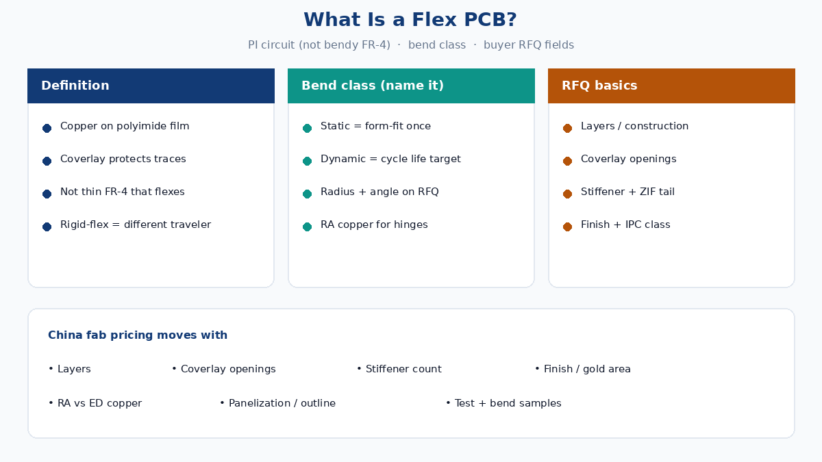
Plain definition: FPC, not bendy FR-4
In fab language, a flexible printed circuit is a copper circuit on a flexible polymer film. Polyimide dominates because it survives soldering temperatures, holds dimensional stability through etch and lamination, and tolerates repeated bend when the copper and coverlay are chosen correctly. Liquid crystal polymer (LCP) and other films appear in niche RF or moisture-critical builds; they are the exception, not the default quote line.
A rigid PCB starts from glass-reinforced epoxy (FR-4 and cousins). That glass weave is what makes FR-4 stiff. You cannot “order FR-4 thinner until it bends like flex” and expect the same reliability. Thin rigid boards can warp and crack; they do not become FPCs. Rigid-flex hybrids exist — rigid FR-4 sections laminated with flex regions — but those are a different traveler and a different quote. If your enclosure only needs a one-time fold and no connector count reduction, ask whether flex is solving a real mechanical problem or just adding cost.
Layer anatomy China fabs actually build
A typical single- or double-sided flex stack is small enough to hold between two fingers, yet every layer shows up on the traveler and the invoice.
Flexible substrate. Polyimide film, commonly 12.5 µm, 25 µm, or 50 µm. Thinner film bends more easily and registers harder. Thicker film raises stiffness and can help static form-fit parts that must hold a shape after install.
Copper foil. Rolled annealed (RA) copper is preferred for dynamic flex because the grain structure tolerates repeated strain better. Electrodeposited (ED) copper is common on static or cost-driven builds. Foil weight (often 1/3 oz, 1/2 oz, 1 oz) trades conductivity and etch yield against bend life. Specifying “1 oz copper, dynamic hinge” without checking RA vs ED is a common RFQ gap.
Adhesive vs adhesiveless. Adhesive-based stacks bond copper to PI with acrylic or epoxy adhesive. Adhesiveless copper-clad laminates put copper directly on PI (or with a very thin tie coat). Adhesiveless builds are thinner, often better for fine pitch and dynamic life, and usually cost more. Buyers should name which construction they need rather than assuming the fab’s “standard flex” matches the bend map.
Coverlay. A polyimide film with adhesive, laminated over the etched copper, with openings cut or lasered for pads, fingers, and test points. Coverlay thickness and adhesive flow change how clean a pad opening looks after press. Opening size, clearance to copper, and registration tolerance are manufacturing variables — not artwork afterthoughts.
Surface finish on exposed copper. ENIG, OSP, immersion silver, soft or hard gold on connector fingers — chosen for solderability, contact wear, and shelf life. Finish choice affects both cost and which processes the fab runs on that panel.
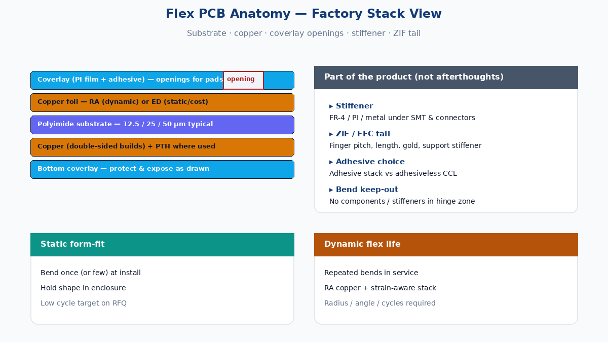
Static form-fit vs dynamic flex life
“Flexible” is not one specification. Buyers must name the bend class on the RFQ, or the fab will price a static part and you may discover a dynamic failure in the field.
Static (form-fit) flex is bent once — or a few times during assembly — and then stays in that shape for the product life. Think folding a circuit into a compact housing, wrapping around a battery, or routing under a hinge that rarely moves after install. Design focus: minimum bend radius for the installed shape, copper elongation during that one fold, and whether the part springs back or must be held by the enclosure. Cycle life targets are low (often tens to hundreds of cycles at most, sometimes effectively one).
Dynamic flex is intended to bend repeatedly in service: notebook hinges, printer heads, camera modules, wearables, robotic joints. Design focus: RA copper, adhesiveless or carefully chosen adhesive stacks, copper on the neutral bend axis where possible, coverlay and copper thickness balanced for strain, and a documented cycle life (for example tens of thousands to millions of bends) with a defined radius and angle. Dynamic builds cost more and scrap differently; a static quote applied to a dynamic hinge is a reliability failure waiting for warranty data.
If the RFQ only says “flex PCB, bendable,” the estimator has to guess. Name static or dynamic, the bend radius, bend angle, cycle target, and which zones may never bend (component areas, connector tails). That single paragraph of mechanical intent changes material, copper type, and test plan.
Coverlay is not solder mask
A frequent buyer myth: “coverlay is just flexible solder mask.” Functionally both protect copper and leave openings for pads. Mechanically and process-wise they are different.
Solder mask on rigid boards is a liquid or dry-film polymer photoimaged onto FR-4. Coverlay on flex is a pre-cut (or laser-cut) PI film laminated with adhesive. Coverlay openings are discrete windows; adhesive squeeze-out and registration dominate yield. Liquid photoimageable (LPI) coverlay / flexible solder mask exists for some fine-feature flex, but many China fab travelers still mean PI film coverlay unless you explicitly call out LPI.
Why it matters on RFQ: opening size below a certain clearance to copper, dense pad arrays, and gold-finger windows all drive laser time, tooling, and scrap. Asking for “solder mask openings like a rigid board” on a PI coverlay stack invites wrong process assumptions. State coverlay type (PI film vs LPI), opening method if you care, and critical opening-to-copper clearances.
Stiffeners and connector tails are part of the product
A bare flex film with components soldered onto unsupported PI will wrinkle under stencil print and crack under connector insertion. Production FPCs almost always include local reinforcement.
Stiffeners are FR-4, PI, or metal (often stainless steel or aluminum) pieces laminated or bonded onto selected zones: under BGAs and connectors, at screw bosses, or to create a pseudo-rigid island for SMT. Thickness, material, adhesive type, and keep-out from the bend zone belong on the drawing. Stiffener count and mix (FR-4 + steel on one part) show up as line items.
ZIF / FFC connector tails are the plated fingers that insert into a zero-insertion-force or flexible flat cable connector. Finger length, pitch, gold plating, and stiffener behind the tail are not “assembly accessories” — they are fab features. A quote that omits stiffener and finger finish is incomplete for any part that plugs into a ZIF housing.
Treat stiffeners and tails as first-class stack features in the RFQ, not as “we’ll add them later.” Later usually means a second CAM spin and a price change.
When rigid plus a harness is enough
Flex earns its cost when it removes connectors, saves volume, survives motion, or replaces a loom that would fail vibration. It does not automatically win every packaging argument.
Stay on rigid + discrete cable or FFC harness when:
- The interconnect is a short, straight run with standard connectors and no tight 3D fold.
- Bend cycles are zero after install and a cheap ribbon or wire harness already meets EMI and impedance needs.
- Layer count and impedance control are easier on FR-4, and the mechanical problem is only “get signal from board A to board B.”
- Volume is low and NRE for a custom flex (tooling, fixtures, bend qualification) exceeds the harness BOM.
Choose flex when the enclosure geometry forces a fold path, when connector count or solder joints are the reliability weak point, when weight and thickness budgets kill FR-4 plus plugs, or when the product hinges and needs a controlled dynamic life. The honest RFQ question is not “can you make flex?” — it is “does flex remove enough connectors, volume, or failure modes to pay for the stack?”
What China fabs actually price and schedule
Overseas buyers often compare unit price alone. Flex quotes move with manufacturing variables that rigid RFQs rarely mention:
- Layer count and construction — single-sided vs double-sided with PTH vs multilayer all-flex vs rigid-flex. Each step adds lamination, drill/laser, and registration risk.
- Coverlay openings — count, minimum size, and whether laser or punch; dense windows raise time and scrap.
- Stiffener count and material mix — each piece is a bond step; steel and selective PI stiffeners cost more than a single FR-4 island.
- Surface finish — ENIG vs selective hard gold on fingers vs OSP; gold area is a real cost driver.
- Copper type and thickness — RA, thin foils, and controlled impedance add material and etch constraints.
- Panelization and outline — odd contours, many NPTH slots, and tight outline tolerances waste panel area and add routing/laser time.
- Electrical test and bend / continuity requirements — flying probe vs fixture, and any mandated flex-cycle sample testing.
- Lead time — adhesiveless materials, special finishes, and rigid-flex often sit on longer material queues than commodity 2L FR-4.
If two quotes differ by 40%, check whether one assumed static ED copper with one FR-4 stiffener and the other assumed dynamic RA, adhesiveless, selective gold, and three stiffeners. Align the traveler before you chase the low number.
Buyer RFQ basics (minimum field list)
Use this short table as a checklist on the first RFQ. It will not replace a full drawing package, but it stops the worst guesswork.
| RFQ field | What to state |
|---|---|
| Bend class | Static form-fit or dynamic; radius, angle, cycle target |
| Layer / structure | 1S / 2S±PTH / multilayer flex / rigid-flex (name it) |
| Materials | PI thickness; adhesive vs adhesiveless; RA or ED copper + oz |
| Coverlay | PI film or LPI; critical opening sizes / clearances |
| Finish | ENIG, OSP, immersion Ag, soft/hard gold on fingers |
| Stiffener | Material, thickness, locations, count |
| Connectors | ZIF/FFC pitch, finger length, plating, supporting stiffener |
| Quality class | IPC-6013 class / type if required; any AQL or test notes |
| Files | Gerber or ODB++, stack drawing, bend map, BOM if assembled |
Ship the bend map as a sketch if needed. A one-page diagram of fold lines and keep-out zones prevents more scrap than another paragraph of adjectives.
Soft next step
If you are defining a flex for the first time, freeze bend class and structure before you argue unit price. Put static vs dynamic, layer construction, coverlay, finish, and stiffener/tail callouts on the RFQ so China fab estimators price the same traveler you intend to qualify. When those fields are clear, a fab can return a quote and DFM notes that match the mechanical job — not a brochure definition of “bendable board.”