
The same BGA site came back a third time. First pass restored continuity. Second pass cleared a cold joint that AOI had flagged after vibration test. Third pass powered the board on the bench, then the unit failed again after a week of thermal cycling in the chamber. The solder looked acceptable under the microscope. The plated through-hole under the pad did not. Heat from three remove-and-replace cycles had eaten the barrel margin that the original double-sided reflow had already started to consume. That is the failure mode this article is about: not the first unpowered glance at a burned board, but the point where controlled rework stops being cheaper than a remake from a China fab.
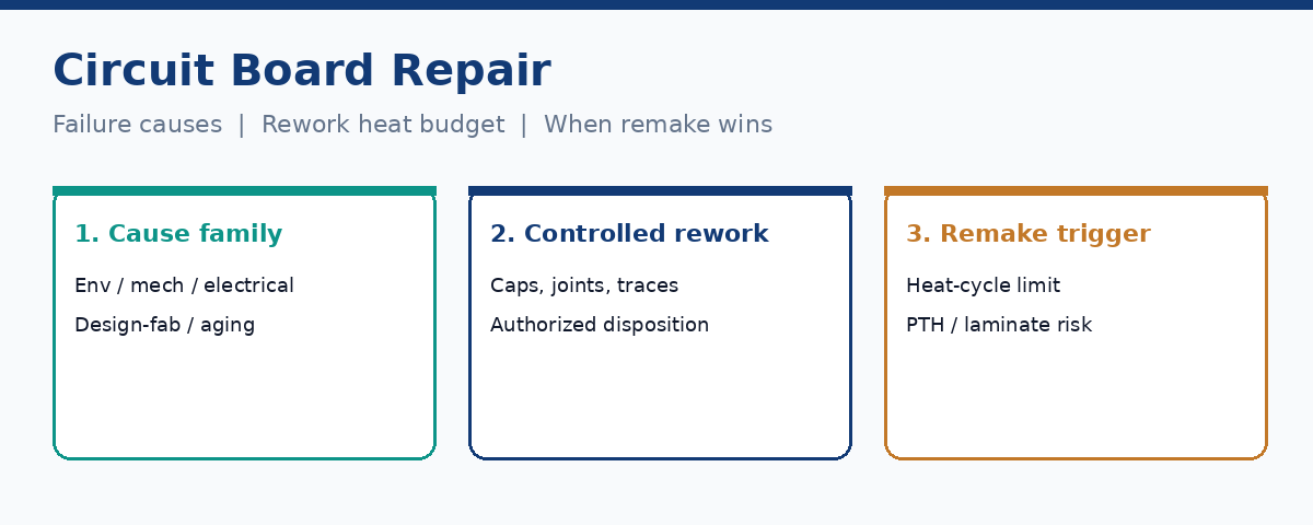
QA, assembly, and field support teams make that call under schedule pressure. The useful frame is failure cause plus heat-cycle budget plus scrap triggers -- then a remake RFQ that captures the weak joint so XFPCB does not rebuild the same risk into the next lot.
Failure families that show up on real boards
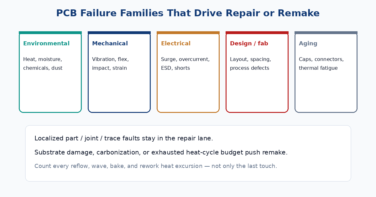
Printed circuit assemblies fail for reasons that cluster, even when the symptom looks like a random reset or a dead rail. Naming the family early keeps the shop from treating every return as a single-part swap.
Environmental stress accumulates quietly. Thermal cycling expands and contracts copper, laminate, and solder at different rates until joints crack or layers separate. Moisture and ionic contamination open corrosion paths and leakage under coatings. Dust and chemical exposure create conductive films that did not exist at first article. Boards that lived near heat sinks, outdoor enclosures, or battery compartments often carry this signature long before they stop powering.
Mechanical stress is more abrupt. Vibration, connector insertion cycles, board flex at mounting points, and drop events crack fillets, lift pads, and fatigue via barrels. Connectors and heavy magnetics take the first hits. A unit that works on the bench and fails after road transport is often telling a mechanical story, not a firmware one.
Electrical abuse leaves different fingerprints. Surges, overcurrent, and ESD can burn traces, open semiconductor junctions, or leave carbonized spots that still leak after the obvious part is gone. A fuse that keeps dying after replacement is pointing at a current path that was never fixed.
Design and fabrication weak points fail early in life when spacing, annular ring, copper weight, or plating thickness left no margin for the duty cycle. Aging finishes the list: electrolytic capacitors dry out, connectors lose spring force, and solder joints that survived first reflow fatigue under years of thermal work.
These buckets overlap. Heat accelerates corrosion. Vibration finishes a joint that moisture already weakened. The diagnostic goal is not a perfect taxonomy -- it is picking the family that explains the repeat failure so rework or remake addresses the cause, not only the last failed part.
Localized repairs assembly shops actually perform
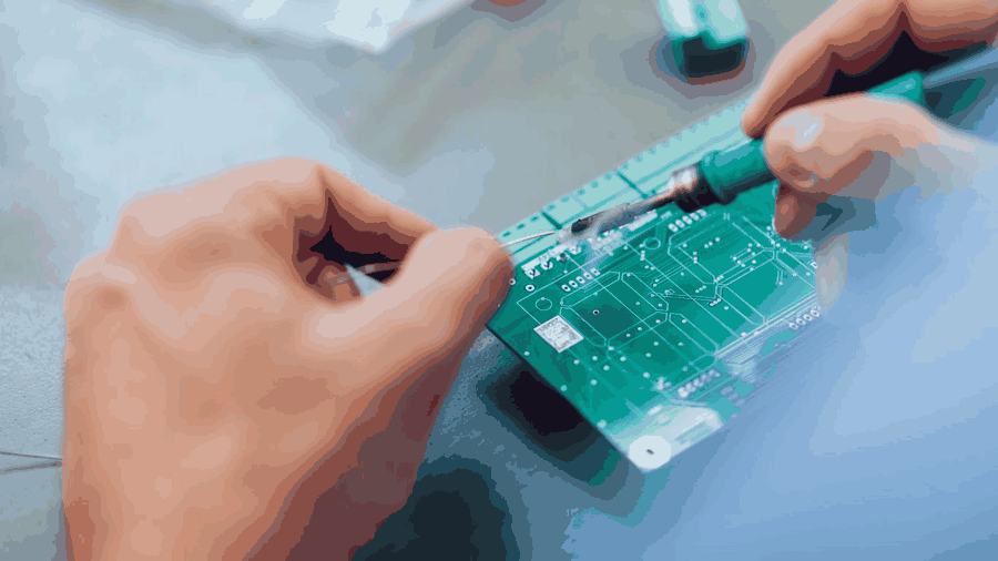
Most recoverable PCBA faults are local. Shops spend their rework time on a short list of jobs that restore the original approved configuration without rewriting the board structure.
Capacitor replacement remains the everyday case. Bulged or leaking electrolytics destabilize rails and create intermittent brown-outs. Controlled removal, site cleaning, correct MPN and polarity, and post-install electrical checks put many consumer and industrial boards back into service when the laminate is still sound.
Solder-joint work covers cold joints, cracked fillets, insufficient wetting, and bridges. Hand tools or hot-air stations reflow or replace the joint after flux and pad cleaning. Intermittent opens that change with temperature often live here -- provided magnification confirms the pad and via are intact before heat is applied again.
Trace and pad repair covers lifted lands, burned surface conductors, and open outer-layer paths. Approved methods under IPC-7711/21 territory include jumper wires, conductive epoxy systems, and discrete land replacement when engineering authorizes a repair that may differ from the original artwork. That distinction matters: restoring the BOM part is rework; restoring function with a different conductor path is repair and usually needs a separate disposition.
BGA, QFN, and fine-pitch packages raise the bar. Removal and replacement need profiled heat, board support, moisture control, and post-process X-ray or other hidden-joint inspection. A board that "powers on" after a BGA swap is not finished until the affected nets pass the same inspection and test path the product requires for release.
None of these jobs are free heat. Every remove-and-replace cycle adds thermal history that the laminate and nearby parts must still survive.
Rework heat-cycle budget and multilayer PTH risk
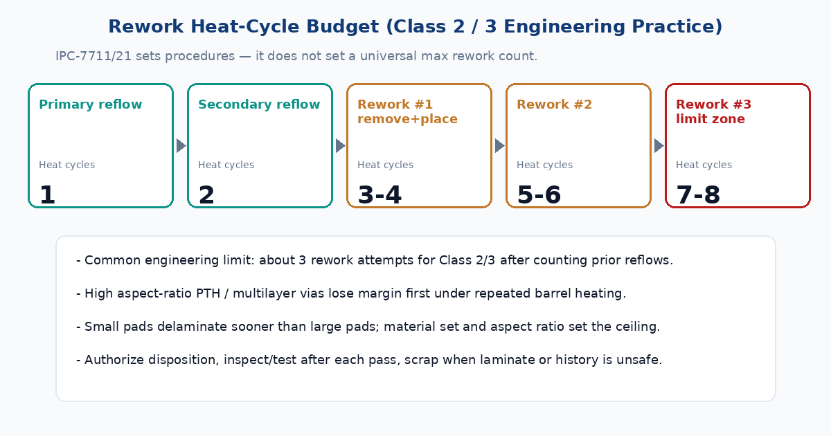
IPC-7711/21 documents rework, modification, and repair procedures. It does not set a hard maximum number of times a printed circuit assembly may be reworked. Process engineers still need a limit, because each heat excursion consumes thermomechanical life that production reflow already started spending.
Count every cycle that took solder near liquidus or baked the stack: primary-side reflow, secondary-side reflow, wave or selective solder where used, bake before moisture-sensitive rework, conformal-coat cure when it heats the board, and each remove-plus-replace pass. For a typical double-sided SMT board, two production reflows are already on the ledger before the first repair station touch. One remove-and-replace often adds two more heat events. Industry practice for many Class 2 and Class 3 designs clusters around three rework attempts when the material set is robust -- roughly six heat cycles of rework-related exposure on top of production history for a well-chosen stack. That is engineering judgment, not an IPC universal number. High layer-count boards with high aspect-ratio plated through-holes lose margin sooner. Small pads delaminate earlier than large pads. Passive process-sensitivity limits can be tighter than the IC next to them.
Multilayer PTH barrels are the quiet failure site after repeated rework. The joint on the surface can look acceptable while the barrel plating fatigues, cracks, or separates from the inner pad. That is how a site "fixed" on the third attempt fails again in the field or in thermal cycling: the copper structure under the package ran out of life. When X-ray, microsection samples from sister boards, or rising open rates on the same RefDes show barrel risk, more heat is the wrong answer.
Authorization belongs before the iron. SHDC-style controlled process language is blunt for a reason: disposition first, then qualified procedure, then post-rework inspection and retest of the affected path. Rework restores the assembly to original approved requirements. Repair may restore function by an approved method that differs from the original design. Touch-up corrects a local workmanship condition. Scrap removes the board from usable production. Operators should not invent jumper routes or substitute MPNs without the authority that owns the traveler.
Scrap and remake triggers that end the rework loop
Rework should stop when the board condition or the history makes reliability unverifiable. Carbonized laminate, serious delamination, blistering, or unknown thermal history are scrap indicators in most quality systems. Lifted pads that cannot be restored within an approved repair procedure, unrecoverable PTH damage, excessive warpage that prevents package alignment, and contamination that cannot be cleaned to the product cleanliness rule belong in the same bucket.
Multiple previous reworks on the same site or serial number deserve an MRB look even when the latest joint looks pretty. If required inspection cannot be performed -- no X-ray access for a hidden joint that needs it, no functional fixture for the affected path -- the board should not ship as "reworked OK." Customer contracts that prohibit the proposed repair method force scrap or return for disposition rather than a quiet shop-floor improvisation.
Economics enter after technical feasibility. Labor, yield risk, and the opportunity cost of skilled rework time can exceed a remake lead time from a China fab, especially when the BOM is still available and the root cause is a design or process weakness that will recur. A high material value alone is not a reason to keep heating a compromised stack.
Remake RFQs that capture the root cause for XFPCB
When remake wins, the RFQ has to carry the failure story. Gerbers alone rebuild the same weak joint. Photograph the site before aggressive cleaning. Name the RefDes, the failure family, and the heat history: how many reflow and rework cycles the site already saw, whether the barrel or pad failed under the joint, and whether sister serials show the same signature.
Call out what to change on the next build. Wider annular ring or filled vias under a power pad, higher Tg or different stackup where delamination started, copper weight on a rail that ran hot, coating where moisture drove corrosion, mechanical support where connectors cracked fillets, or an AVL-locked capacitor series that survives the duty cycle. If assembly is in scope, state IPC class, AOI and X-ray expectations on the packages that failed, and whether first-article microsection or thermal cycling is part of acceptance.
XFPCB uses that package as manufacturing input. A remake that documents why the old board died is how buyers avoid paying twice for the same intermittent open. Controlled rework remains the right move for localized, authorized, heat-budgeted fixes. Once the third cycle at a multilayer site starts looking like the first cycle all over again, the smarter spend is a new board built to the lesson, not another remove-and-replace on exhausted plating.