
LED boards fail in the field less often from “wrong optics math” than from layout and construction choices that fab and assembly cannot rescue: broken thermal copper, unmarked polarity, FR-4 used where a metal-core was required, or MCPCB chosen without a heatsink plan. This article owns LED board layout that survives fab/assembly—thermal copper continuity, polarity discipline, and FR-4 vs MCPCB decision gates. It is not a duplicate of thermal-path-before-MCPCB deep dives; those cover heat-path physics first. Here the buyer and layout lead freeze what the plant must build and what the SMT line must orient.
Buyer decision frame: electrical + thermal + construction
Before RFQ, write three decisions:
- Power class — indicator LEDs vs general lighting vs high-power COB clusters.
- Construction — FR-4, aluminum MCPCB, copper-core, or ceramic (rare, expensive).
- Heat exit — board copper only, board to chassis, or MCPCB to extruded heatsink with TIM.
If construction and heat exit disagree, no amount of via stitching saves lumen maintenance. Name construction on the RFQ cover. Product context: LED PCB Board and Metal Core PCB; assembly context: LED PCB Assembly.
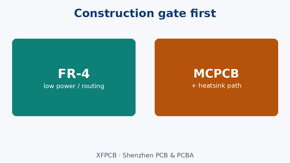
FR-4 vs MCPCB: decision gates (not a brochure)
Choose FR-4 when: power is low, LEDs are indicators or sparse, enclosure airflow is enough, cost and multilayer signal routing matter more than metal-core thermal conductivity, and you need plated through-holes for complex circuitry on the same board.
Choose aluminum MCPCB when: sustained LED power creates heat the FR-4 stack cannot spread into a heatsink path, the board is essentially a single- (or limited-) layer lighting module, and mechanical attach to a metal fixture is planned.
Choose copper-core / exotic when: power density or CTE matching demands it—and budget and fab capability are confirmed in EQ, not assumed from a catalog photo.
Do not choose MCPCB when: you still need a dense multilayer digital section on the same outline without a hybrid plan; or you have no heatsink/TIM path—metal core without an exit is only a warmer paperweight. Hybrid modules (FR-4 driver + MCPCB LED daughter) are often more honest than forcing one exotic board to do everything.
Thermal copper continuity on the layout
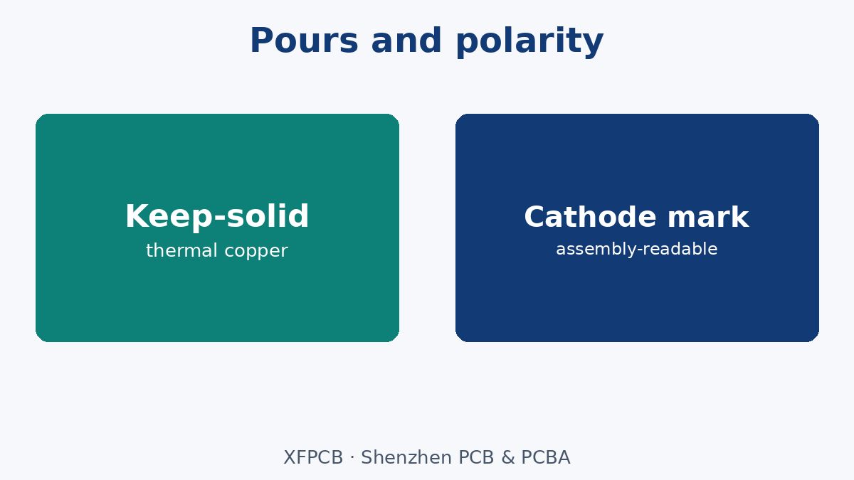
Whether FR-4 or MCPCB, copper under and around LED thermal pads must be continuous toward the heat exit. Common fab-killing mistakes:
- Isolated thermal pads with no pour connection.
- Slots, logos, or silk that carve necks in the pour.
- Mounting holes that sever the pour without thermal bridges.
- Thermal vias that stop on an inner plane that is not connected to the heatsink side.
- On MCPCB: assuming the metal base replaces the need for correct dielectric and pad design—still follow the vendor’s thermal pad and isolation rules.
Call out on fab notes: keep-solid thermal regions, via arrays under LED pads (FR-4), dielectric and base thickness for MCPCB, and whether the metal base is anodized/insulated on the back. Do not invent conductivity percentages—freeze constructions and attach datasheets.
Polarity, cathode marks, and assembly survival
LED polarity errors are expensive because optical testing may come late. Layout and fab must cooperate:
- Silkscreen cathode/anode marks that survive mask and are readable after reflow.
- Pick-and-place polarity in the centroid matching the silk and the datasheet.
- For connectors and polarized electrolytics on driver sections, same discipline.
- Avoid silk under LEDs where height or optics forbid it—use pinside marks or assembly drawings.
Assemblers on LED SMT lines still need unambiguous marks. “Everyone knows the flat side” is not a traveler note.
Current balance and power trunk layout
Parallel LED strings need matched branch impedance—trace length, width, and via count. Series strings need voltage budget honesty. Layout rules that survive fab:
- Wide trunks for high current; do not neck down under silk art.
- Dual-end feed on long strips when voltage drop would dim the far end.
- Sense lines and driver placement close enough that feedback is real.
- Heavy copper callouts when current demands them—finished copper, not folklore.
Etch compensation on fine features matters less than unbroken wide pours for power; still, do not let CAM add thieving slots across a thermal or power pour you marked keep-solid.
Optical spacing vs thermal spacing vs DFM
Symmetry helps brightness uniformity; spacing must also leave:
- Solder-mask dams and paste apertures that assemble cleanly.
- Clearance for pick nozzles and rework.
- Copper area for heat—not only optical pitch.
High-density arrays look good in renders and fail in thermal and stencil EQ. Freeze min pitch with both optical and manufacturing owners.
Failure modes buyers see
- Early lumen drop / color shift — thermal path broken; wrong construction; TIM missing.
- One string brighter — parallel imbalance; trunk resistance.
- Whole row dead after SMT — polarity or tombstoning on tiny LEDs; paste aperture issues.
- MCPCB warped / not flat to heatsink — unbalanced copper; wrong stack; poor machining flatness callout.
- Dielectric breakdown to base — MCPCB clearance/isolation violated.
- Driver overheat on FR-4 section — heat from LEDs conducted into driver island without thermal break or heatsink plan.
Fab can hold copper continuity and isolation rules you wrote. Fab cannot invent a heatsink your industrial design omitted.
What fab / assembly can and cannot fix
Can: build FR-4 or MCPCB to frozen stack; keep thermal pours solid; drill thermal via arrays; mark polarity per files; control outline flatness notes for MCPCB; assemble with polarity checks when AOI programmed.
Cannot: turn FR-4 into MCPCB performance after Gerbers; fix a missing chassis thermal interface; recover wrong LED orientation after conformal coat; balance parallel strings that are laid out asymmetrically without an ECO.
RFQ and drawing callouts
- Construction: FR-4 / Al-MCPCB / other—with thickness and dielectric notes for metal-core.
- Copper weight and keep-solid thermal regions.
- Thermal via requirements under LED pads (FR-4).
- Polarity marking method and assembly drawing reference.
- Surface finish compatible with LED pads and wire-bond/COB if used.
- Flatness / bow-twist expectations for heatsink mate (your numbers).
- LED MPN list and any optical binning notes for assembly.
- Heatsink / TIM responsibility (customer vs turnkey).
Common EQ loop
- Board designed on FR-4 to save cost.
- Prototype in open air looks fine.
- Enclosed fixture cooks LEDs; field failures.
- Late switch to MCPCB without changing mounting and TIM.
- Second EQ finally aligns construction, layout pours, and mechanical heat exit.
Break the loop with a construction gate in schematic/layout kickoff—not after tooling.
Stencil, paste, and LED package DFM
Tiny LED packages tombstone when paste volume and pad symmetry are wrong. Large high-power packages void when paste and thermal pad apertures fight each other. On the assembly RFQ:
- Confirm paste aperture design ownership (customer vs assembler).
- Call out thermal-pad paste patterns recommended by the LED vendor—do not invent your own void targets as marketing numbers; follow the datasheet process window.
- For double-sided boards, sequence reflow so heavy LEDs are on the side the process can support.
- Avoid silk or mask that creates dams where paste must wet.
Fab supplies the pads; assembly owns paste—but pad geometry on the Gerber is still a layout responsibility. EQ early when using new LED packages.
White solder mask, reflectivity, and cosmetic class
Lighting products often specify white mask for reflectivity. White mask has process quirks (coverage, cosmetics, contrast for AOI). Call cosmetic class and whether AOI expects white mask contrast challenges. Do not assume green-mask DFM rules transfer unchanged. If optics require black mask in some zones and white in others, freeze openings and color breaks on the drawing—mixed mask is an EQ topic, not a surprise.
Creepage, isolation, and offline LED drivers
Mains-powered LED drivers on the same or adjacent boards need creepage/clearance that survives humidity and pollution degree for the market. Metal-core boards complicate isolation to the base—follow MCPCB dielectric withstand rules and keep screw bosses from shorting across isolation. Layout that ignores safety spacing will fail certification regardless of luminous efficacy. Put safety spacing notes on the fab drawing when offline voltages are present; XFPCB builds to your frozen gaps—it does not redesign safety architecture.
Panelization and singulation for lighting boards
LED strips and modules often panelize with V-score or mouse bites that must not crack thermal pours or leave burrs that hurt heatsink flatness. Call singulation method and keep-outs from LED packages to score lines. MCPCB routing/milling differs from FR-4 punch habits—confirm outline method with the plant. Depanel stress can crack solder joints on large LEDs if fixtures are wrong—assembly and fab must share the panel drawing.
Test points and optical test access
Electrical test and optical binning need access. Do not cover obligatory test pads with LEDs or deep cups. If integrating spheres or fixtures need keep-outs, put them on the mechanical drawing. Functional LED test at PCBA should be named on the test menu (see inspection/test map sister note)—brightness checks are not the same as bare-board electrical.
Cost traps without invented prices
MCPCB everywhere “to be safe” inflates cost when FR-4 plus heatsink would work. FR-4 everywhere “to be cheap” inflates warranty when power density is real. Decorative copper logos that slot thermal pours look branded and run hot. Skipping polarity silk to clean optics creates scrap. Align construction with power and enclosure first.
COB and high-density clusters
COB modules concentrate heat. Layout must assume the substrate and attach method are part of the optical engine. Call out keep-outs for bond wires, dam materials, and phosphor processes if applicable—or treat COB as a bought module with pad geometry frozen. Do not improvise COB pads from an SMD LED footprint library.
Driver section coexistence
When drivers share the board with LEDs, decide thermal zoning: copper pours that deliberately separate heat, or separate boards. Switching regulators next to hot LED pours raise component temperatures and can modulate brightness through thermal drift. Put thermal keep-outs on the drawing. EMI from drivers also couples into long LED trunks—pair supply/return and minimize loop area as with any power layout.
Aluminum PCB vs generic “metal core” language
Buyers sometimes write “aluminum PCB” when they mean any MCPCB, or “MCPCB” when they need a specific dielectric thickness and thermal conductivity class. Freeze the stack: copper weight, dielectric type/thickness, aluminum grade/thickness, and back-side finish. See also Aluminum PCB for product framing—still put the stack numbers on your drawing. Vague metal-core language produces quotes that are not comparable and boards that do not match the thermal model.
Field wiring and connector strain on lighting PCBs
Screw terminals and wire harnesses on LED drivers stress pads if the chassis does not strain-relieve the cable. Layout should place connectors where the enclosure supports them, with adequate copper anchors and keep-outs from hot LED pours. Vibration in outdoor fixtures turns weak connector land patterns into intermittent opens that look like “LED failures.” Mechanical and layout reviews must meet before fab.
Documentation pack for lighting RFQs
Attach LED datasheets (thermal pad drawings), MCPCB or FR-4 stack, polarity legend, heatsink/TIM sketch, and panel drawing. Optical bin codes belong on the assembly traveler if the product sells bins. Without that pack, CAM and SMT guess—and lighting tolerances are unforgiving once fixtures are tooled.
Closing: layout that the oven and the heatsink both accept
LED PCB success is construction choice plus copper continuity plus polarity discipline plus a real heat exit. Freeze FR-4 vs MCPCB gates early, draw thermal pours the plant must not slot, mark polarity so SMT cannot guess, and put heatsink/TIM ownership on the RFQ. XFPCB builds LED boards and assemblies when those notes are clear—bring the gates to the first quote, not to the first returned fixture.
One release checklist line worth repeating: construction gate signed, thermal pour keep-solids drawn, polarity marked, heatsink path owned. If any box is empty, the lighting PCB is not ready for CAM—regardless of how good the photometric spreadsheet looks.