
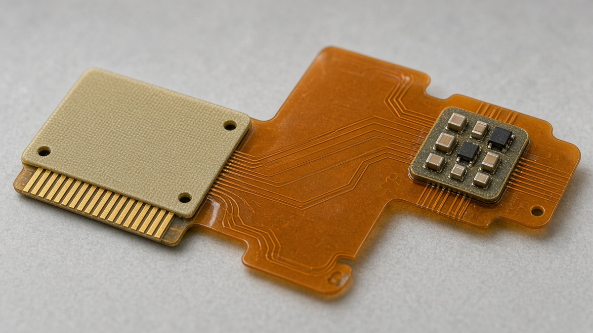
Most flex stiffener scrap does not come from picking the wrong catalog material name. It comes after the material is already ordered: the adhesive class does not survive the reflow the island must see, the stiffener edge sits on a copper neck that later tears, or the assembly line treats a local FR4 patch as a full panel carrier and the unsupported flex flaps through paste print. FR4 versus polyimide is still a real choice—but the buyer questions that move yield are how it is bonded, where the stiffness step lands, and what holds the circuit on the SMT line.
This article is written for that slice of the problem. Application selection (connector vs SMT vs metal duty) lives in our FPC stiffener applications playbook. Finished ZIF/FFC insert-zone thickness and pad-side rules live in the connector-tail DFM guide. Build-level choice between stiffened multilayer flex and true rigid-flex lives in multilayer flex with stiffeners vs rigid-flex. Here the focus is narrower: FR4 versus polyimide as a bonding and edge-fatigue decision, and how that decision couples to assembly carriers on a flexible PCB product.
What “stiff enough” actually has to survive
A bonded stiffener sees a short, harsh life before the product ever ships:
- Bond process (PSA press or thermal bond cycle).
- Any subsequent wet process or finish if the stiffener is already on.
- Bake, paste print, placement, and reflow if the island carries SMT.
- Connector insertion and latch force if the island is a mate zone.
- Housing screws, operator handling, and field vibration or thermal cycle.
FR4 and polyimide both can look “rigid” on a desk. They fail differently under that list. FR4 brings high flexural stiffness and a large modulus step at its outline. Polyimide film stiffeners bring a milder modulus step, better chemical kinship with the flex stack, and less “brick edge” feel—but they will not hold a heavy connector or a tall reflow island the way FR4 does. Metal (stainless / aluminum) is a third family with sharper edges and its own bond chemistry; this article stays on FR4 versus PI film because that is the pair most RFQs still leave underspecified.
If your product already needs multilayer rigid circuitry or plated through owned by a rigid stack, stop here and reopen the build choice—stiffener bonding will not invent a Type 4 construction. For local islands only, keep reading.
FR4 vs polyimide: decide from process load, not habit thickness
Buyers often inherit a note that says “0.3 mm stiffener” with no material. Plants then quote FR4 or PI interchangeably and the first article teaches you which one they assumed. Reverse the order: name the loads, then pick the material that can carry them without creating an edge crack path you cannot live with.
When FR4 is the honest answer
Choose FR4 when at least one of these is true:
- The island must stay flat under paste print and reflow for a real SMT cluster (QFN, fine discretes, small BGA).
- A connector or housing applies sustained clamp or screw load through the stiffened zone.
- Operators will treat the island as a handle during assembly—FR4 forgives finger force that crumples thin PI film.
- You need a drilled or routed feature in the stiffener (clearance hole, tooling slot) that a thin film cannot provide cleanly.
FR4 costs you a sharp stiffness step. That is acceptable when the outline is kept out of the bend and away from pad roots, and when the adhesive class matches the thermal path after bond.
When polyimide film is the honest answer
Choose PI film when:
- The job is mainly thickness build and mild reinforcement on a flex tail—not a reflow trampoline for a dense SMT island.
- Height budget forbids the FR4 thickness you would need for the same feel.
- The stiffener edge must sit closer to a form region than FR4 would tolerate, and you need a softer modulus transition.
- The bond chemistry and flex stack are both polyimide-family, and you want to avoid FR4’s CTE mismatch at the bond line under thermal cycle.
PI film is the wrong default under heavy SMT or screw bosses. It will pass a thickness check and still wrinkle in reflow or peel under clamp.
The decision that RFQs skip
Ask one question before material: After bond, what is the highest temperature and mechanical load this island must still see? If the answer is “reflow plus insertion,” FR4 with a thermoset-class bond is usually the working pair. If the answer is “room-temp mate only, light handling,” PI film with a qualified PSA often suffices. If the answer is “we do not know,” do not freeze either material—freeze the process profile first.
| Load after bond | Lean FR4 | Lean PI film | Do not leave TBD |
|---|---|---|---|
| Reflow on the island | Yes | Only if height forces it and parts are light | Adhesive class + carrier plan |
| Repeated ZIF/FFC mate | If clamp/buckle demands it | Common for thickness build | Edge vs pad-root keep-out |
| Screw / housing clamp | Yes | Rarely | Bond peel at temperature |
| Dynamic bend nearby | Only with generous edge keep-out | Milder step, still needs keep-out | Outline vs bend map |
| Temporary SMT support only | Possible, but confirm vs real carrier | Weak as sole carrier | Separate pallet / frame |
Bonding RFQ: PSA vs thermal bond is a traveler decision
Material without adhesive class is half a stiffener. The bond line is where FR4 and PI diverge in process, not in brochure language.
PSA (pressure-sensitive)
PSA suits many room-temperature or low-heat attaches: connector thickness build, light handling islands, some PET/PI film jobs. It is fast and reworkable in some plants. It is a poor bet when the island later sees full lead-free reflow, sustained high temperature, or screw clamp through FR4. Soft PSA under FR4 after reflow is a classic “stiffener walked” failure—pads look fine, the island is no longer where CAM thought it was.
RFQ fields for PSA: adhesive family or fab process name, required peel class if you have one, maximum temperature after attach, and whether the bond is allowed before or after coverlay/finish.
Thermal / thermoset bond
Heat-and-pressure (or thermoset epoxy-class) bonds earn their keep when the island must survive reflow or high peel. They need controlled press cycles and usually cost more process time. For FR4 under SMT, this is often the only honest path. For PI film under reflow-light duty, thermoset still helps if peel at temperature matters.
RFQ fields for thermal bond: bond temperature/pressure class the fab will run (or “fab thermoset stiffener process”), sequence relative to coverlay and surface finish, and any bake-out required before bond.
Sequence mistakes that look like material failures
- Bonding FR4 with PSA, then sending the island through reflow: peel or slide blamed on “bad FR4.”
- Bonding after selective finish in a way that contaminates the bond area: voids at the edge that open in thermal cycle.
- Mixing PSA on the connector tail and thermoset on the SMT island without labeling both on the traveler: operators use one press recipe for both.
Write adhesive per island when a board has more than one stiffener duty. One vague “stiffener adhesive TBD” line invites a single shop default across incompatible loads.
What to demand at first article for the bond
- Visual: no lifted corners, no adhesive squeeze-out into bend or pad openings.
- Registration: outline vs copper/coverlay within the tolerance you froze.
- Peel sample or fab equivalent when the island sees reflow or screw load—agree the method before FA, do not invent a number here.
- Measured finished thickness in connector insert zones (detail and tolerance window belong with the connector datasheet and the connector-tail guide—not a blog millimetre).
Edge fatigue: the failure mode stiffener quotes hide
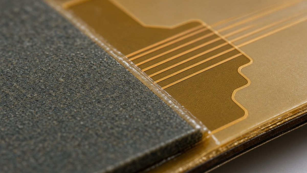
The stiffener edge is a stiffness cliff. Copper, coverlay, and adhesive see elevated strain there during bend, insertion, latch clamp, and thermal cycle. Field returns that say “flex cracked near connector” are often edge-fatigue stories, not mysterious polyimide defects.
How FR4 edges fail
FR4’s high modulus makes a clean, abrupt step. Fatigue and first-insert tears prefer:
- Stiffener outline ending at or under a pad root.
- Traces crossing the edge at a sharp angle or necked down at the step.
- Vias sitting on the edge line.
- Coverlay that ends at the same station as the FR4 (stacked discontinuities).
- Dynamic bend that starts at the FR4 end instead of after a keep-out.
Routed FR4 outlines with rough or nicked edges act as crack starters. Ask how the fab cuts FR4 stiffeners (route, punch, laser) and whether the edge facing the bend is deburred or drawn with a radius/chamfer note when the duty is harsh.
How PI film edges fail
PI film fails more often by peel and crease than by a brittle crack, but copper still fatigues at the step if the film is thick enough to matter. Thin PI can hide a false sense of safety: the edge looks soft, yet a short stiffener still dumps insertion buckle into the pad root. Edge keep-out still applies; “it is only PI” is not a keep-out waiver.
Design moves that cut edge risk (without redesigning the whole flex)
- Keep the stiffener outline out of the designed bend region; leave a keep-out between stiffener end and bend start sized to your thickness and duty—confirm with fab, do not freeze a blog millimetre as capability.
- Run traces straight across the edge where they must cross; avoid acute angles and neck-downs on the step.
- Pull vias and unused pads back from the edge.
- Overlap coverlay under the stiffener edge so dielectric and stiffener steps are not coincident.
- For connector tails, treat stiffener-edge vs pad-root spacing as a controlled dimension—see the connector-tail guide for insert-zone specifics; do not conflict two drawings with different mm targets.
- Optional strain-relief bead of flexible adhesive along the edge is a process option some products use; call it out if you want it, do not assume the fab adds it.
Inspection timing matters
Edge cracks discovered at final inspection after N insertions were often born at first mate or at FA. Build a simple gate:
- After bond / before SMT: outline registration and bond integrity.
- After reflow: look at the edge for lift, whitening, or coverlay fracture.
- After first mate (connector products): inspect pad roots and stiffener end under magnification.
- After a defined handling or cycle sample on FA: catch fatigue early, not after a field lot.
When the stiffener is not your SMT carrier
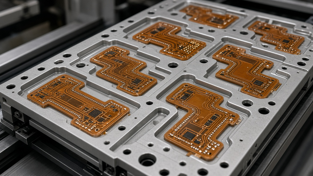
Local rigidity is not panel rigidity. A common assembly failure mode: the drawing shows a 20 mm × 30 mm FR4 island under a QFN cluster, and the line runs the flex through a printer as if that island were a rigid board. The island stays flat; the surrounding flex flutters; paste smears; placement offsets; the post-mortem blames “flex warpage” or the stiffener material.
Three support architectures
1. Stiffener-only local support
Works when the panelization already includes a rigid frame, or the flex is small and the island covers nearly the whole part area that must print. Still verify vacuum or rail support for anything outside the island.
2. Stiffener + assembly carrier / pallet
The permanent stiffener does its product job; a reusable carrier holds the panel flat through print, place, and reflow. Windows in the carrier clear components and connector zones. This is the honest default for most production FPCs with sparse islands.
3. Stiffener as handle only, full panel frame for SMT
Some builds add breakaway FR4 rails or a frame that is routed off after assembly. The product stiffener can then be PI film sized for the connector, while the frame (not the product island) carries the line. Do not confuse disposable panel rails with the product stiffener on the RFQ—price and CAM differ.
Carrier RFQ callouts buyers forget
- Will this part run on a carrier? If yes, who designs the pallet (customer or factory), and who owns window cutouts around stiffener height?
- Maximum stiffener stack height the carrier must clear (FR4 + adhesive + any dual-side build).
- Second-side support if the flex is double-sided SMT—carriers must clear first-side parts.
- Whether vacuum nesting is required because PI film islands do not seal like FR4 boards.
- Bake-out ownership before reflow (polyimide moisture)—carrier and bake fixtures are part of the same plan.
FR4 islands that are tall and sparse can interfere with a flat carrier if windows are wrong. PI film islands that are thin can leave the circuit unsupported inside a carrier window. Material choice and carrier design are one conversation.
Double-sided and multi-island boards
Two FR4 islands on opposite faces can balance warp—or fight the carrier. Call out bond sequence and which face sits in the nest. Multiple islands on one face need a carrier that supports between islands, not only under them; otherwise the flex between FR4 bricks becomes a hinge during print.
FR4 vs PI bonding matrix for the traveler
Use this as a working matrix when both materials could hit thickness but only one survives the process:
| Question | If answer is A → | If answer is B → |
|---|---|---|
| Highest temp after bond | Reflow / high bake → thermoset + usually FR4 for SMT islands | Room-temp mate only → PSA + PI film often enough |
| Mechanical clamp | Screw or hard latch → FR4 + high-peel bond | Light insertion only → PI film candidates |
| Edge proximity to bend | Tight → prefer PI film and enforce keep-out; reconsider layout | Generous keep-out → FR4 acceptable |
| SMT density on island | Real IC cluster → FR4 + carrier plan | None / passives only → PI may suffice |
| Who holds the panel on the line | Local island only → add carrier or frame | Panel rails already rigid → stiffener can be product-only |
| Dual stiffener duties on one FPC | Split materials/adhesives per island on the drawing | Single habit material for all → expect compromise scrap |
Capability and drawing notes that prevent silent defaults
Our flexible PCB fabrication capability review is where plants confirm coverlay, stiffener materials, and bond processes they actually run. On the drawing or controlled process sheet, freeze at least:
- Per-island material (FR4 or PI film—not “stiffener”).
- Nominal stiffener thickness and whether it is a thickness-build or stiffness-first duty.
- Adhesive class (PSA vs thermoset) per island.
- Bond sequence vs coverlay / finish.
- Side relative to pads / components.
- Outline with edge keep-outs from bend and from critical pad roots.
- Edge finish expectation for FR4 if duty is harsh (route quality / chamfer note).
- Assembly support plan: stiffener-only, carrier, or panel frame—and who owns the carrier.
- FA gates: bond visual, registration, thickness where relevant, post-reflow edge check, post-mate check for connector products.
If two islands share one vague note, CAM will optimize for the loudest habit in the shop—not for your mixed loads.
Failure symptoms → likely process miss
| What you see | Likely miss | First corrective ask |
|---|---|---|
| Stiffener corner lifted after reflow | PSA under reflow, or contaminated bond | Switch adhesive class; check sequence |
| Crack / copper open at stiffener end after mate | Edge on pad root or zero bend keep-out | Move outline; reinforce keep-out; review FR4 edge quality |
| Paste smear / placement shift outside island | No carrier; island treated as full board | Add pallet / frame; redesign support |
| Connector will not latch / intermittent contact | Finished thickness or contact side wrong | Return to connector-tail stack worksheet—not a material swap alone |
| PI island wrinkles under QFN | Material too soft for SMT duty | FR4 or real carrier + lighter parts |
| FR4 island OK but flex tears at edge in thermal cycle | CTE step + coincident coverlay/via | Soften step (PI), move vias, overlap coverlay, keep-out |
| Second-side parts crushed | Carrier / support ignored first-side height | Carrier window redesign; print sequence |
What to freeze before the next stiffener RFQ
Do not send another RFQ that only names “FR4 or PI, 0.3 mm.” Walk this list and fill every line on the traveler:
- Loads after bond — reflow? screw clamp? repeated mate? dynamic bend nearby?
- Material per island — FR4 for hard SMT/clamp islands; PI film for thickness build and milder edges; never one habit for mixed duties.
- Adhesive class per island — PSA only where temperature and peel allow; thermoset where reflow or clamp demands it; sequence vs coverlay/finish named.
- Edge map — stiffener end vs bend start, vs pad roots, vs vias; FR4 edge quality note if needed.
- Carrier architecture — stiffener-only, stiffener + pallet, or panel frame; owner of carrier windows; second-side clearances.
- FA gates — bond, registration, thickness where the connector cares, post-reflow edge, post-mate for connector products.
- Boundaries — application map, connector-tail thickness, and rigid-flex build choice stay in their own playbooks; do not smash conflicting millimetre targets onto one balloon.
Any blank line is where a plant default will quietly decide your edge fatigue and your SMT yield. Fill the blanks before you argue about another tenth of a millimetre of foil.